





















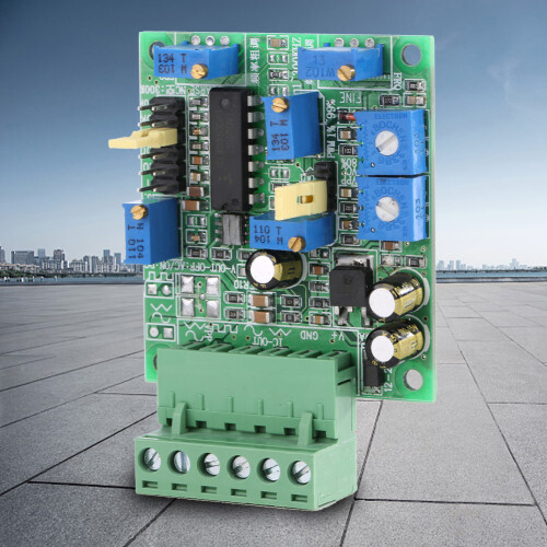
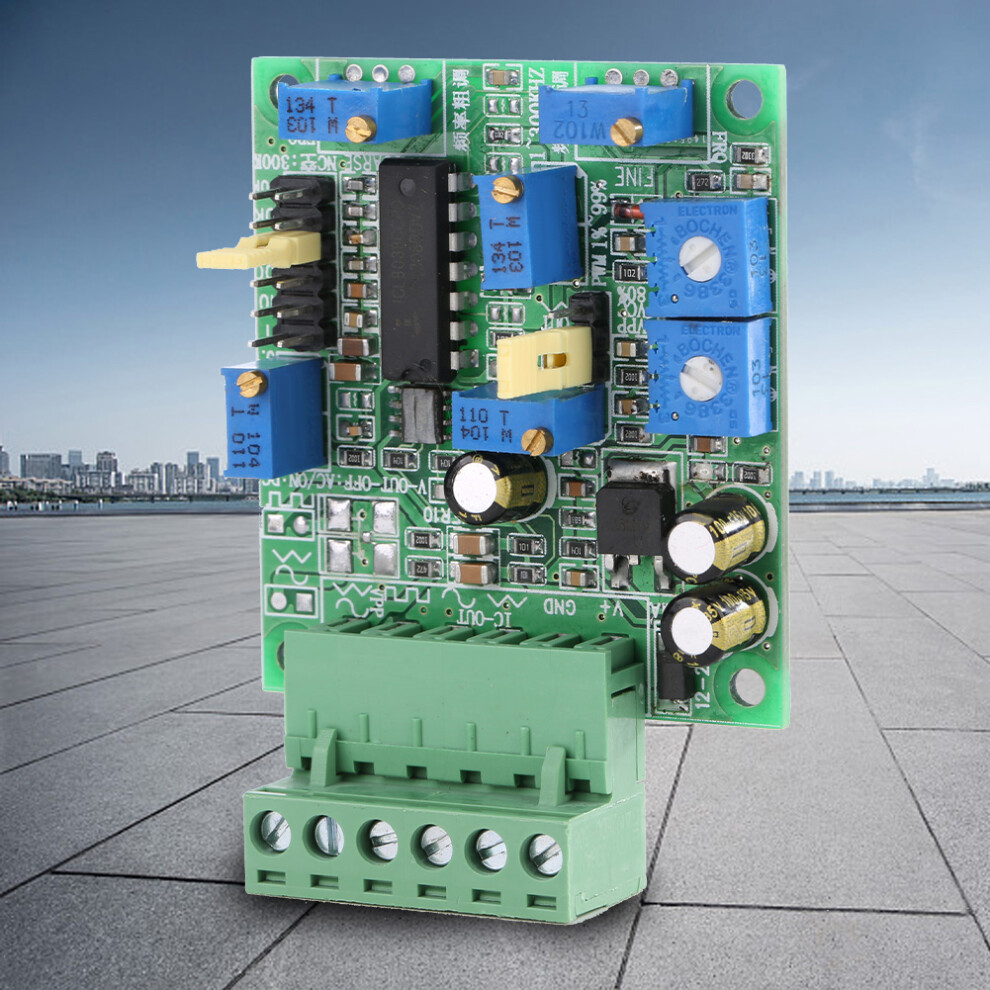
SG-8038 Voltage Controlled Signal Generator with Sine Triangle Square Waves
In stock
Smart shoppers OnBuy it!
- Earn Cashback on every purchase – spend it instantly on your next order
- Free delivery – on millions of items across the site
- Customers love us – 130,000 Trustpilot reviews and an 'Excellent' rating
Interest-free payment options available


See full product description & details
Delivery: Standard (Free) | Mon 10th - Wed 12th Aug
Returns: 30 days
180-day payment protection
You might also like
Summary
- A Signal generator capable of producing sine, triangular, and square wave outputs.
- The output signal frequency and duty ratio remain unchanged when the power supply signal changes by adding a stabilized power supply. The output signal is more stable.
- Add anti - connect anti - reverse protection for power input.
- Frequency shift setting the shift pin to 7 range.
- Frequency regulation is divided into fine adjustment and fine adjustment 2 multi - turn precision potentiometer, high precision of frequency control.
SG-8038 Voltage Controlled Signal Generator with Sine Triangle Square Waves Description
SG-8038 DDS Signal Generator Sine Triangle Square Wave Board Module
Overview:
Features:
A Signal generator capable of producing sine, triangular, and square wave outputs.
The output signal frequency and duty ratio remain unchanged when the power supply signal changes by adding a stabilized power supply. The output signal is more stable.
Add anti - connect anti - reverse protection for power input.
Frequency shift setting the shift pin to 7 range.
Frequency regulation is divided into fine adjustment and fine adjustment 2 multi - turn precision potentiometer, high precision of frequency control.
Specification:
Condition:
Weight: 32g/1.1oz
Model: SG-8038
A. Function and use
2.11. Cooling mode: natural cooling (the normal operating temperature is not more than 40 degrees).
2.12. Use: can not be placed in other heating equipment, to avoid dust, oil mist, corrosive gas, humidity and strong vibration places. Flammable gases, conductive dust or liquids are prohibited.
2.13. Operating temperature: -15~+45 c.
2.14. Working humidity: 40%~90%.
2.15. Permissible vibration: less than 10-55hz / 0.15mm
2.16. Storage temperature: -20 to +65
2.17. Space interference waves: no requirement
B.Performance index parameters:
1. Mechanical structure and electronic circuit parameters of the main machine
3.1.2. Input current and power consumption:
Minimum standby current: 35MA/24V
Maximum allowable operating current: 75MA/24V
Allowable starting surge peak maximum current: 1A
3.1.3 allowable input power ripple: 200MV
3.1.4. Frequency adjustment range: 1hz-350khz, 7-gear dual-precision multi-turn potentiometer adjustment, high precision of frequency control.
3.1.6.PWM duty cycle is adjustable from 5% to 100%
3.1.9. Amplifier output signal current capacity 20MA/ circuit
3.1.10. Triangular wave and sine wave signals straight out of the chip have the smallest distortion but weak driving ability. In addition, the low end of the wave type of this signal is not to the ground (that is, floating ground, there is bottom noise, raise a certain amplitude on the ground wire and then waveform. All ICL8038 chips are like this. If you want e these two interfaces, you should pay attention to whether they match the external circuit of the user.
3.1.11. Module startup time. The time between the module being powered on and the normal signal output. The output time of the amplifier is relatively long, ranging from 2 to 3 seconds. During this time, the waveform amplitude increases from slow full to set value. This amplifier can play the role of power buffering. Reduce the impact of terminal.
Operating instructions and others:
A. Sine wave debugging:
1. Adjust PWM to 50%.
2. The frequency FRQ jumping pin and potentiometer are set to OK.
3. THD distortion -LH2 potentiometer has small symmetrical distortion in wave mode.
4. VPP potentiometer output amplitude up and down without cutting the top.
B. Square wave and PWM debugging:
1. Setting of frequency FRQ jumper needle and potentiometer is OK.
2. VPP potentiometer output amplitude upper and lower top edge not hypotenuse. Try to be a right Angle.
3. Duty cycle required for setting square wave in PWM potentiometer.
C. Triangular wave debugging:
1. Adjust PWM to 50% (positive triangular wave)
2. Set PWM to <50% (positive sawtooth wave)
3. Set PWM to >50% (anti-aliasing wave)
4. The frequency FRQ jumping pin and potentiometer are set to OK.
5. VPP potentiometer output range does not cut the top
D. Some basic concepts about signals.
AC signal: signal wave energy alternates between GND ground wire and GND ground wire.
DC signal: signal wave energy changes alternately above GND ground wire.
FRQ: F = 1 / T
PWM DUTY = HT / + LT (HT) * 100%
Different wave types, the various value calculation formula is different. To consult the table calculation, or with the instrument measurement. There are many types of V values, commonly used as follows:
PEAK value, PEAK value VPP, average value VAVG, true effective value T-VRMS, effective value/RMS VRMS
Package List:
1 x Signal Generator Module
Note:
2. Straight triangular wave and sine wave signals from the chip have the smallest distortion but weak driving ability. In addition, the low end of the wave type of this signal is not to the ground (that is, floating ground, there is bottom noise, raise a certain amplitude on the ground wire and then waveform. All ICL8038 chips are like this. If you want e these two interfaces, you should pay attention to whether they match the external circuit of the user.
3. Module startup time. The time between the module being powered on and the normal signal output. The output time of the amplifier is relatively long, ranging from 2 to 3 seconds. During this time, the waveform amplitude increases from slow full to set value. This amplifier can play the role of power buffering. Reduce the impact of terminal. Must be evaluated before use. This power on delay, slow start function can meet the customer's requirements, whether there is a conflict.
4. It is suggested e a lower frequency under the premise of meeting the use requirements. This will improve job stability.
5. When the PWM is adjusted to 100%, the output has no waveform and is always in a high level state. Therefore, when setting the potentiometer adjustment in PWM, do not overdo it (do not overdo it clockwise). If you overdo it, you will not see the waveform output. If it is found that there is no waveform output, the multi-turn PWM regulating potentiometer can be rotated counterclockwise until there is waveform output (when the counterclockwise is turned to the end, there is also 5%-10%PWM with waveform output, and the minimum PWM duty cycle ratio will be different with different frequencies). The multi - turn precision potentiometer used in this product is 24 - turn.
6. If the square wave or rectangular waveform with very precise frequency and duty ratio is required, please note that PWM setting will affect the slight change of frequency, and the PWM and frequency shall be adjusted back and forth to achieve the desired accuracy. In addition, if the PWM output amplitude modulation is too low, it will affect the duty cycle measurement accuracy and waveform distortion degree of PWM.
7. For very precise sinusoidal waveforms, note that when adjusting the peak and trough of two THD potentiometers, they will interact with each other, but only slightly. If the requirements are very high, this will be back and forth to adjust thd-l, H these two potentiometers to meet the requirements. In addition, in order to output the sine wave, there is a premise: PWM amplitude potentiometer must be adjusted to the maximum output, determined to be 50% of the duty cycle, and then to correct the thd-l /H two potentiometers, in order to achieve high precision sine wave output.
Details
| OPC | PSJFZST |
|---|---|
| Codes | 3011389394144 (EAN) |
Compare Sellers for SG-8038 Voltage Controlled Signal Generator with Sine Triangle Square Waves
- New from £21.17
| Seller | Ratings | Warranty | Returns | Price | Delivery | Total | Quantity |
|---|---|---|---|---|---|---|---|
| (2 reviews) | - |
30 Days
Free Returns No
|
£21.17
|
+Free Delivery
Est. Delivery:
10th-12th Aug
|
£21.17
|
Earn as you shop with instant Cashback on everything.
No catch, no cost
- Paid into your OnBuy account
- Spend it on your next purchase
- Save it or withdraw it
Become a Cashback VIP
Just 1 purchase unlocks bigger deals & rates